|
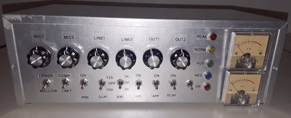
Max Audio Processor - Circuit Description
- Mic Level Inputs - Two discrete microphone pre-amplifiers may be used to connect microphones of low and high impedance, balanced, D-104, and powered mics (phantom & electret), etc Note that while microphones requiring “phantom” power may be used with the MAX Audio Processor, there is no 45 volt supply included in the design. An external phantom interface device is recommended in this case. The builder assumes full responsibility for any microphone damage, should the processor be altered to provide direct phantom power.
- Line Level Inputs - Two separate balanced or unbalanced line inputs are provided to interface to other audio gear or receiver output for aircheck activities.
- Phase Inverter - Half of an un-committed op-amp is utilized as a phase inverter, which may be used to correct situations were the predominant peaks are negative. When in the normal position, the op-amp is removed from the signal path.
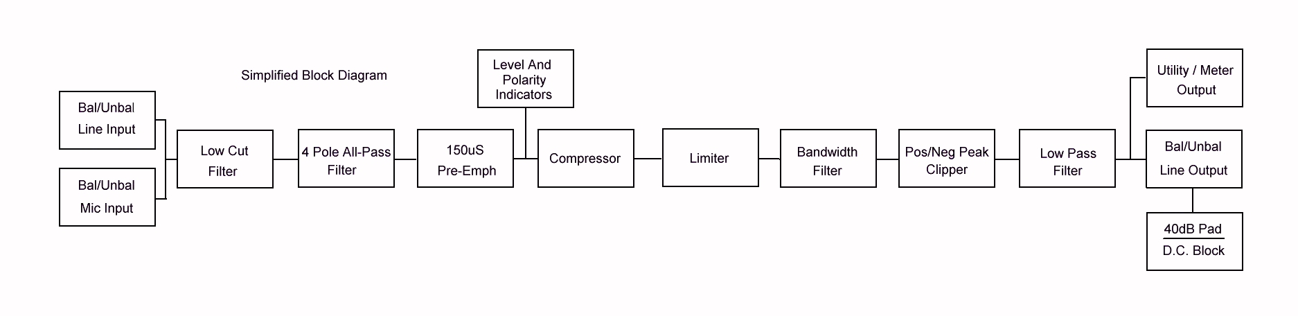
- Low Cut Filter - Also known as a "high pass filter" this circuit attenuates frequencies below the communications vocal range. Background noise such as rumble or vibrations from amplifier fans and power supplies are significantly reduced with this feaure enabled. It has the added benefit of enhancing clarity when the MAX Audio Processor is set for narrow bandwidths by allowing the important 300-3000 Hz vocal range to be emphasized.
- All Pass Filter/Phase Rotator - This function has been a part of every broadcast audio processor since the 1980s due to its ability to increase average modulation levels without changing gain. Compressors reduce gain based on the higher of either positive or negative peaks so asymmetrical waveforms, common with speech, cause unnecessary gain reduction. By rotating the polarity of the incoming signal throughout its frequency range, the overall waveform becomes more symmetric, resulting in less gain reduction (louder audio). The circuit is referred to as an all pass filter because it is acoustically transparent unless the speaker is wearing headphones. In this case, the effect can be heard since the path of audio to the ears through the jaw and from the headphones will be neither in nor out of phase.
- Pre-Emphasis - This R/C circuit uses a 150uS time constant and approximately 12dB of boost in the important vocal range. It is enabled by default to counteract the inherant loss of higher frequencies by narrow bandwidth receivers and to improve the signal to noise ratio in the 2-5 kHz presence range. The 150uS curve was chosen for its effectiveness in voice communication over the 3 to 7 kHz range of the MAX processor.
- Compressor - The compressor section is designed to provide effective transmitted audio control. User selectable settings range from a mellow "open" sound for casual conversations during good band conditions (default) to a significantly aggressive mode for challenging conditions and contesting. Even this setting maintains enough dynamic range to preserve "sonic cues" that aid in intelligibility. The compressor function can also be disabled for use in noisy operating areas.
- Gain Gate - This is not an expander nor a noise gate as it does not lower or cut off the input. Instead, this circuit reduces background noise by preventing any increase in gain when the input to the MAX processor drops below a preset level. When active, the MAX provides full compression and limiting above the threshold and switches to unity gain below. The threshold was chosen to have a minimal effect and typically acts only on low level noise.
- Limiter - The high ratio (15:1) limiter is part of the same chip that provides compression so the two function well together. Its main function is to tightly control the amount of drive to the clipping section to ensure maximum modulation without the distortion that results from overdriving clippers.
- SCAF Adjustable Bandwidth Filter - Bandwidth is controlled by two MAX295 SCAF (Switched CApacitor Filter) chips wired in tandem. This arrangement provides a moderately steep roll off of frequencies above the set point while minimizing audible artifacts. The filter frequency is determined by a three position switch, offering 3, 5, and 7 kHz frequency response (6, 10, and 14 kHz bandwidth).
- Clipper - The clipper significantly increases the amount of transmitted audio by eliminating the peaks that add nothing to perceived loudness. With these unecessary peaks clipped off, average modulation levels can be increased noticably before reaching -100% (AM), triggering an ALC cutback (SSB), or reaching maximum deviation limits (FM). This clipper circuit features absolute -100% peak control and a user selectable +100% (all modes) or +125% (AM only) peak control. While it is possible to defeat the positive peak clipper, doing so poses a very high risk of damage to modulation transformers and RF components due to exceeding component breakdown voltages. The clipper circuit is defaulted on for this reason.
- Line Level Outputs - Two discrete line-level outputs provide balanced or unbalanced low-impedance interconnection to two transmitters. Either one may be high level, or low-level with the 40dB pad, and may be AC or DC coupled, as needed.
- Utility Outputs - These two outputs are single-ended, and may be used to drive a VU meter, headphones, a third transmitter, or any other desired external devices.
|